LIFT Reports Drill Results from Yellowknife Lithium Project, NWT
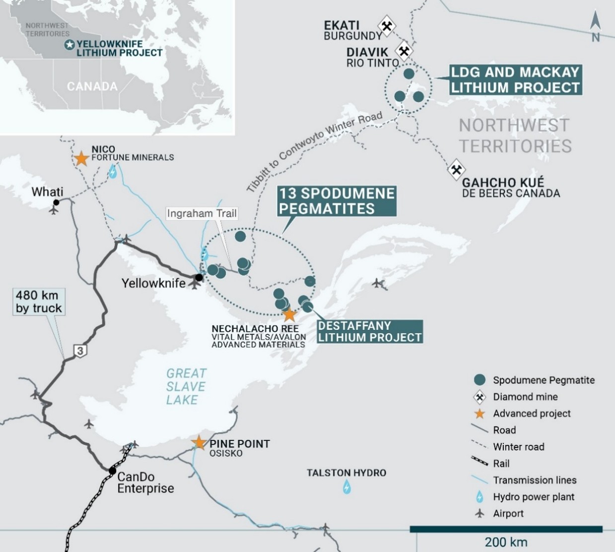
VANCOUVER, British Columbia, June 30, 2026 (GLOBE NEWSWIRE) -- Li-FT Power Ltd. (“LIFT” or the “Company”) (TSXV: LIFT) (ASX:LFT) (OTCQX: LIFFF) (Frankfurt:WS0) is pleased to report results from the 2026 winter and 2025 summer programs completed at the Yellowknife Lithium Project (“YLP”), located outside the city of Yellowknife, Northwest Territories (Figure 1).
This news release provides results from 20 holes drilled on the YLP, for a total of 5,324 m. Seventeen of these holes (4,778 m) were drilled as part of the 2026 winter program and three (546 m) were drilled as part of the 2025 summer work program.
Highlights from the results reported in this news release include:
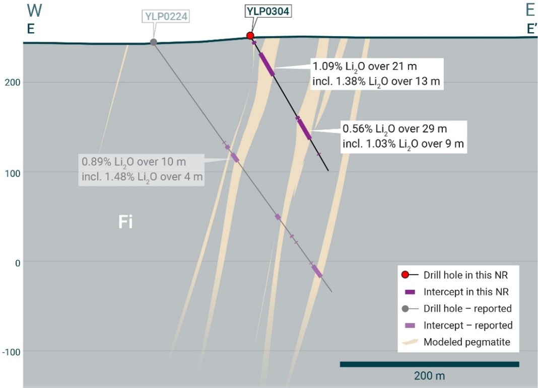
YLP-0304: 21 m at 1.09% Li2O (Fi Main) Including 13 m at 1.38% Li2O
YLP-0306: 18 m at 1.41% Li2O (Ki)
YLP-0312: 26 m at 1.29% Li2O (BIG East) Including 17 m at 1.65% Li2O
YLP-0315: 22 m at 1.09% Li2O (BIG East)
YLP-0320: 17 m at 1.32% Li2O (BIG East)
Figure 1 – Location of LIFT’s Yellowknife Lithium Project (YLP) in the NWT.
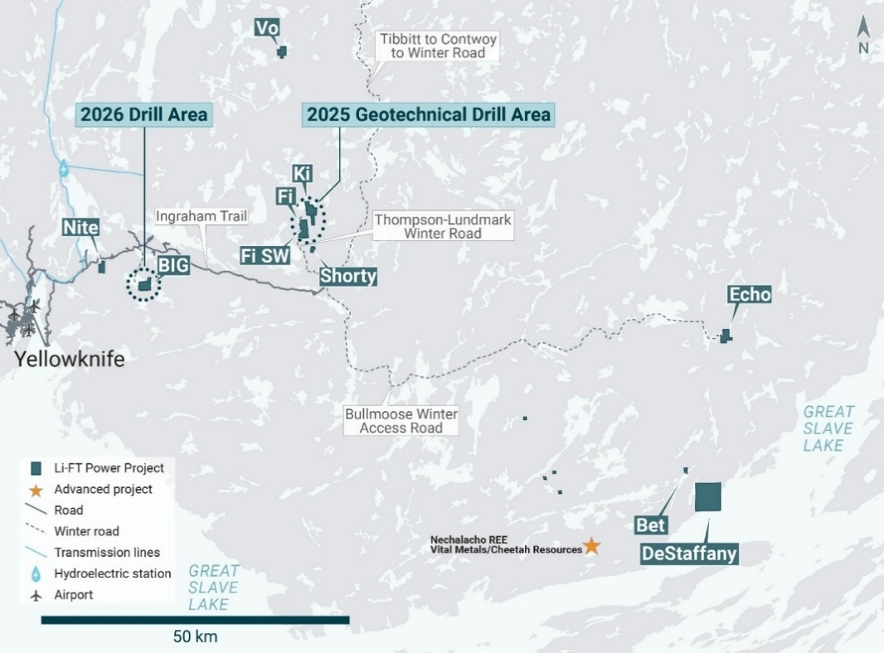
Figure 2 – Location of LIFT’s BIG, Fi Main (Fi), Fi SW, and Ki pegmatites within the YLP.
The seventeen 2026 holes were all drilled in the BIG area of the YLP (Figure 2), marking the first drill campaign at BIG since publication of the inferred mineral resource released to the TSXV in October 2024 and ASX on 22 May 2026.1
The three holes from the 2025 program were drilled on the Fi Main, Fi SW, and Ki pegmatites (Figure 2) and underwent geotechnical strength testing before geochemical analysis.
Discussion of Results
BIG pegmatite
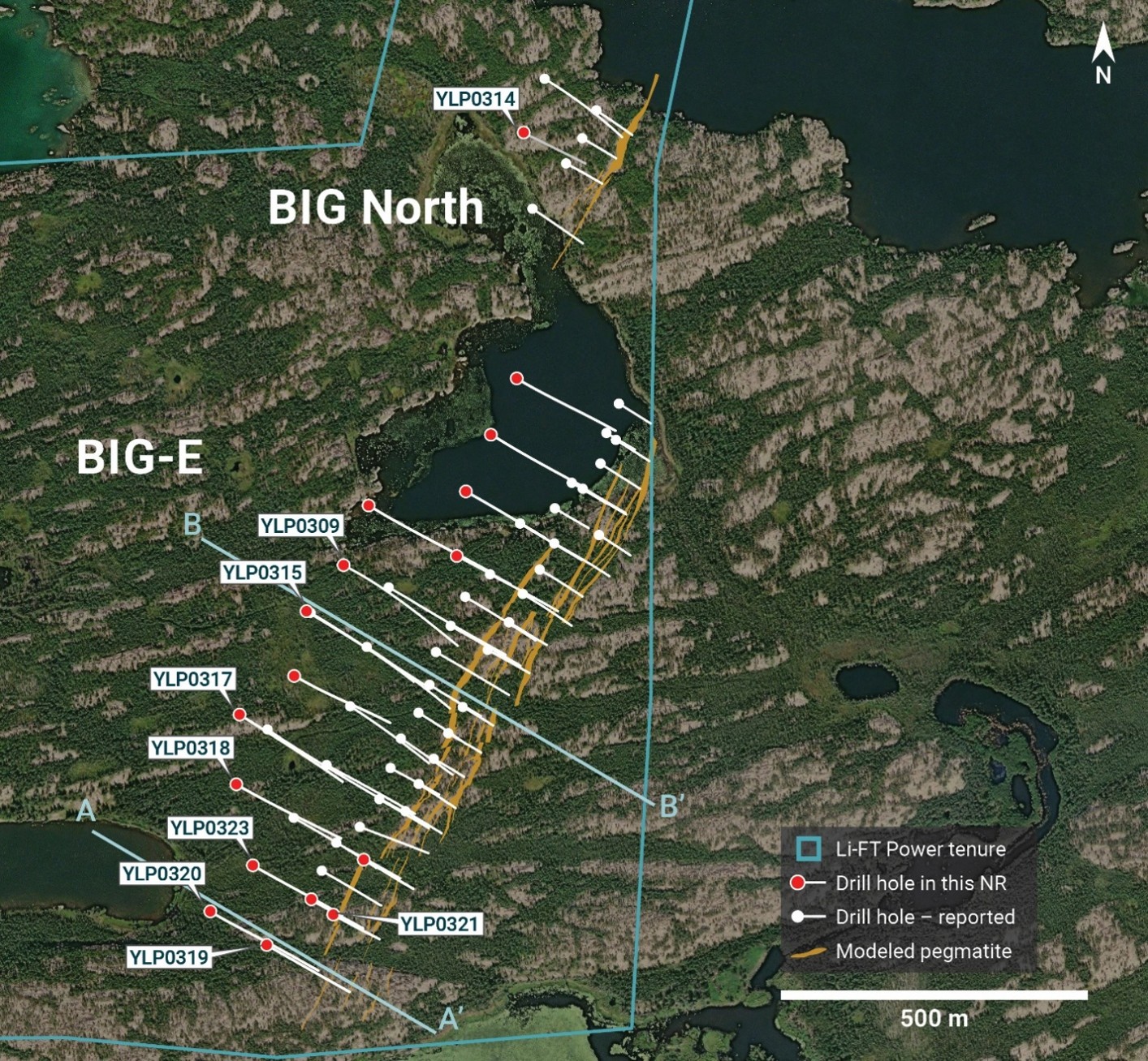
The BIG area includes the BIG East, West, and North pegmatites, with BIG North representing either a separate complex from BIG East or its fault-offset northern extension. Sixteen of the 2026 holes were drilled on the BIG East pegmatite, and one hole was drilled at BIG North (Figure 3).
pzo
News by QuoteMedia - http://www.quotemedia.com
Copyright (c) 2026 QuoteMedia, Inc.
YLP-0324
54.0–65.0 m
11.0 m
1 % Li2O
YLP-0313
198.0–208.0 m
10.0 m
1.1 % Li2O
YLP-0305
71.0–92.0 m
21.0 m
0.5 % Li2O
YLP-0322
101.0–110.0 m
9.0 m
1.1 % Li2O
Intercepts extracted and reviewed by Strikepoint from the issuer’s filings. True widths may differ from downhole widths; see the full release for drill orientation.
The BIG East pegmatite complex comprises a north-northeast trending corridor of parallel-trending dykes that is exposed for at least 1.8 km of strike length, ranges from 10-100 m wide, and dips approximately 55°-75° to the west. Spodumene-bearing pegmatite may occur either as a single dyke 20-35 m wide, or as two to four dykes of similar cumulative thickness within corridors up to 65 m wide. The holes drilled as part of the 2026 winter program extend along 1,000 m of strike length and reach depths of 50 to 300 m below surface.
The BIG North pegmatite comprises a north-northeast trending dyke swarm exposed over at least 350 m of strike length, ranging from 10-35 m in width, and dipping approximately 70° west.
Figure 3 – Plan map showing BIG tenure boundary, pegmatite dykes, 2023-2024 drill holes2, and the 2026 winter drill holes.
Collar geographic locations and assay highlights are provided in Appendix 1.
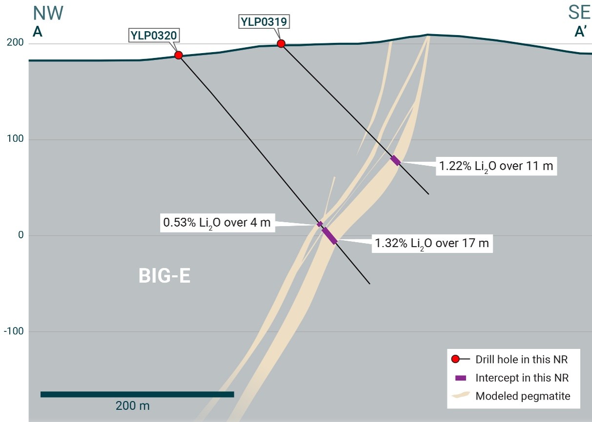
YLP-0319 and 0320 are the most southerly holes drilled on the BIG East complex, testing 100 and 200 m below surface respectively. YLP-0320 returned the better grades, intersecting a 20-m-wide pegmatite dyke that assayed 1.32% Li2O over 17 m (Appendix 1, Figure 4), leaving the BIG East mineralized system open to the south and at depth.
YLP-0319 was drilled 100 m up-dip of YLP-0320 and cut through a 59-m-wide corridor, hosting five pegmatite dykes with cumulative width of 19 m. The thickest of these dykes returned a wall-to-wall composite of 1.22% Li2O over 11 m (Appendix 1, Figure 4).
Holes YLP-0321, 0322, and 0323 were drilled on a section 100 m north of YLP-0319 and 0320. At around 50 m below the surface, YLP-0321 drilled through a 100-m-wide corridor that hosts eight pegmatite dykes with a cumulative width of 28 m. Four of these dykes are spodumene-bearing, with the better composites including 1.24% Li2O over 5 m and 1.08% Li2O over 5 m (Appendix 1).
Figure 4 – Section A-A’ (refer to Figure 3) looking northeast and showing the BIG East pegmatite as well as results from 2026 drilling.
YLP-0322 was designed to test the same corridor approximately 50 m downdip of YLP-0321 and intersected seven dykes totalling 33 m of pegmatite across a drilled width of 75 m. Four of these dykes are spodumene-bearing, returning intersections of 1.15% Li2O over 9 m, 0.97% Li2O over 10 m, 0.57% Li2O over 5 m, and 0.53% Li2O over 2 m (Appendix 1).
YLP-0323 was drilled to test a further 100 m downdip of YLP-0322, intersecting a 54-m-wide corridor with four dykes that sum to 33 m of pegmatite and returning composites of 0.82% Li2O over 6 m and 1.30% Li2O over 1 m (Appendix 1).
YLP-0318 and 0324 were drilled on a section 100 m north of the section with YLP-0321 to 0323. Hole YLP-0324 returned the better grades and was designed to test 50 m below surface and 50 m up-dip of YLP-00683, which was drilled in 2023. Drilling intersected three dykes totalling 16 m of pegmatite over a drill width of 49 m, with the widest returning 1.04% Li2O over 11 m (Appendix 1).
YLP-0318 was drilled 250 m downdip of YLP-0324 and 100 m downdip of 2023 drill hole YLP-01013, intersecting a 92-m-wide corridor with nine dykes totalling 37 m of pegmatite. Spodumene contents are generally low, with the best intersections returning 0.65% Li2O over 3 m and 0.67% Li2O over 2 m (Appendix 1).
YLP-0317 was drilled a further 100 m north of the section with YLP-0318 and 0324, to test the BIG East corridor 300 m below the surface and 125 m downdip of YLP-0115, which was drilled by LIFT in 2023. The drill hole intersected a 32-m-wide pegmatite dyke with negligible spodumene mineralization.
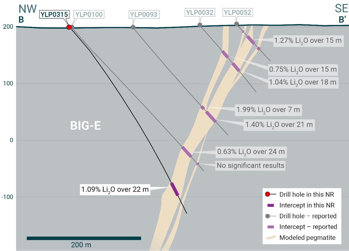
Figure 5 – Section B-B’ (refer to Figure 3) looking northeast and showing the BIG East pegmatite.4
Holes YLP-0316 was collared 100 m north of YLP-0317 to test the BIG East complex at approximately 300 m below surface and 100 m downdip of YLP-0117, drilled by LIFT in 2023.4 New drilling intersected a 22-m-wide pegmatite dyke at the expected depth but with negligible spodumene.
YLP-0315 was collared on a section 100 m north of YLP-0316, near the center of the complex, to test the pegmatite corridor at 200 m below surface and LIFT’s 2023 holes YLP-0093 and YLP-0100.4 New drilling intersected a 24-m-wide pegmatite dyke that returned 1.09% Li2O over 22 m (Appendix 1, Figure 5).
YLP-0309 was collared 100 m further north to test the central part of the BIG East corridor at 200 m below surface, as well as 50 m downdip of hole YLP-0077, drilled by LIFT in 20234. New drilling intersected a 27-m-wide pegmatite dyke with an interval of 10 m averaging 0.66% Li2O, including 1.13% Li2O over 4 m (Appendix 1).
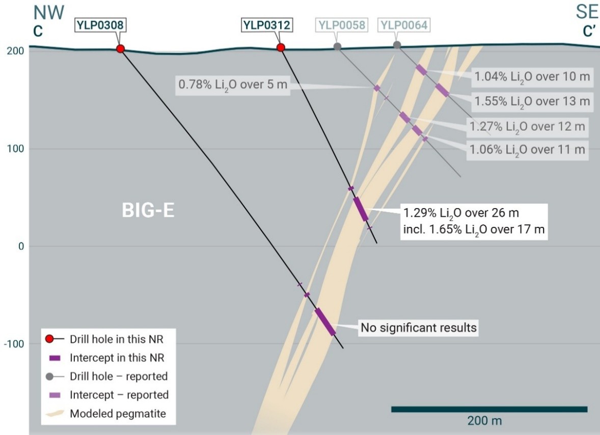
YLP-0312 and 0308 were drilled on a section 100 m north of YLP-0309, to test the BIG East corridor at 175 m and 275 m below surface, respectively. YLP-0312 tested 100 m down-dip of YLP-0058, drilled by LIFT in 2023,4 and intersected a 26-m-wide pegmatite dyke that returned a wall-to-wall composite of 1.29% Li2O over 26 m, including 17 metres averaging 1.65% Li2O (Appendix 1, Figure 6).
YLP-0308 was drilled an additional 100 m downdip of YLP-0312, intersecting four pegmatite dykes totalling 45 m within a drilled width of 57 m, but with negligible spodumene.
Figure 6 – Section C-C’ (refer to Figure 3) looking northeast and showing the BIG East pegmatite.5
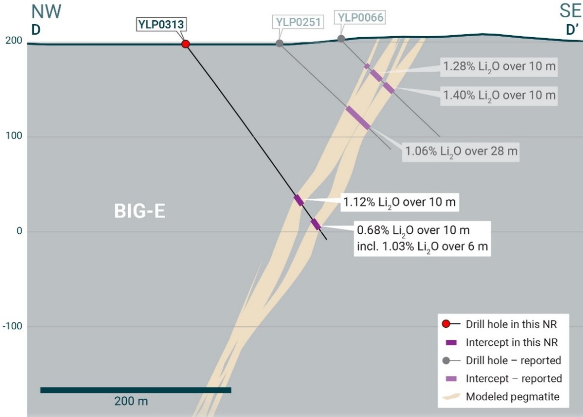
Figure 7 – Section D-D’ (refer to Figure 3) looking northeast and showing the BIG East pegmatite.5
YLP-0313 was collared 100 m north of YLP-0312, to test the BIG East complex at 175 m below surface and 100 m downdip of YLP-0251, drilled by LIFT in 2024.6 New drilling intersected 12- and 10-m-wide dykes spaced 22 m apart, with the upper one returning 1.12% Li2O over 10 m and the lower one 0.68% Li2O over 10 m, including 6 m of 1.03% Li2O (Appendix 1, Figure 7). Mineralization on this section remains open at depth.
YLP-0310 and 0311 were drilled at the north end of the BIG East pegmatite to, respectively, test 100 m downdip of LIFT’s 2024 drill holes YLP-0271 and YLP-0267.6 Both new drill holes intersected 20- to 30-m-wide pegmatite at their expected depths, with negligible spodumene.
YLP-0314 was the only hole drilled at BIG North in the winter 2026 program targeting 100 m downdip of 2023 drill hole YLP-0129.6 No pegmatite was intersected.
Fi Main Pegmatite
The Fi Main pegmatite complex crops out over at least 1.5 km of strike length within a north-south striking corridor that dips between 70°-85° to the west. The dyke can be split into several structural domains, each ~400 to 500 in strike length, that include stretches comprising just a single 25-30 m thick dyke or two or more dykes of similar cumulative thickness within a broader corridor that is up to 150 m wide.
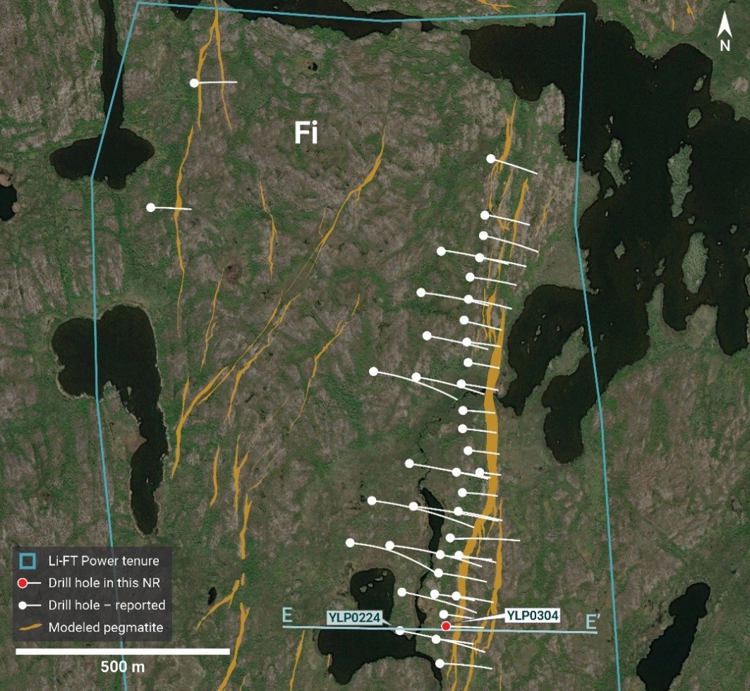
YLP-0304 was drilled in the southern part of Fi Main (Figure 8), where it split into two thick dykes, for the purpose of collecting whole-core material for rock mechanics testing. Assays from the upper dyke returned 1.09% Li2O over 21 m, including 1.38% Li2O over 13 m, whereas the lower dyke assayed 0.56% Li2O over 29 m with a 9-m subinterval averaging 1.03% Li2O (Appendix 1, Figure 9).
Fi SW Pegmatite
The Fi Southwest (SW) pegmatite complex is exposed over at least 1.1 km on surface and occurs within a broader corridor that is 50-100 m wide and dips between 60°-80° to the east. The complex is cored by a 20-40 m wide dyke that is continuous for at least 800 m along strike, with numerous sub-parallel subsidiary dykes between 1-5 m in width. At its northern and southern ends, the main dyke splays out into a broader corridor with more dykes that have narrower widths.
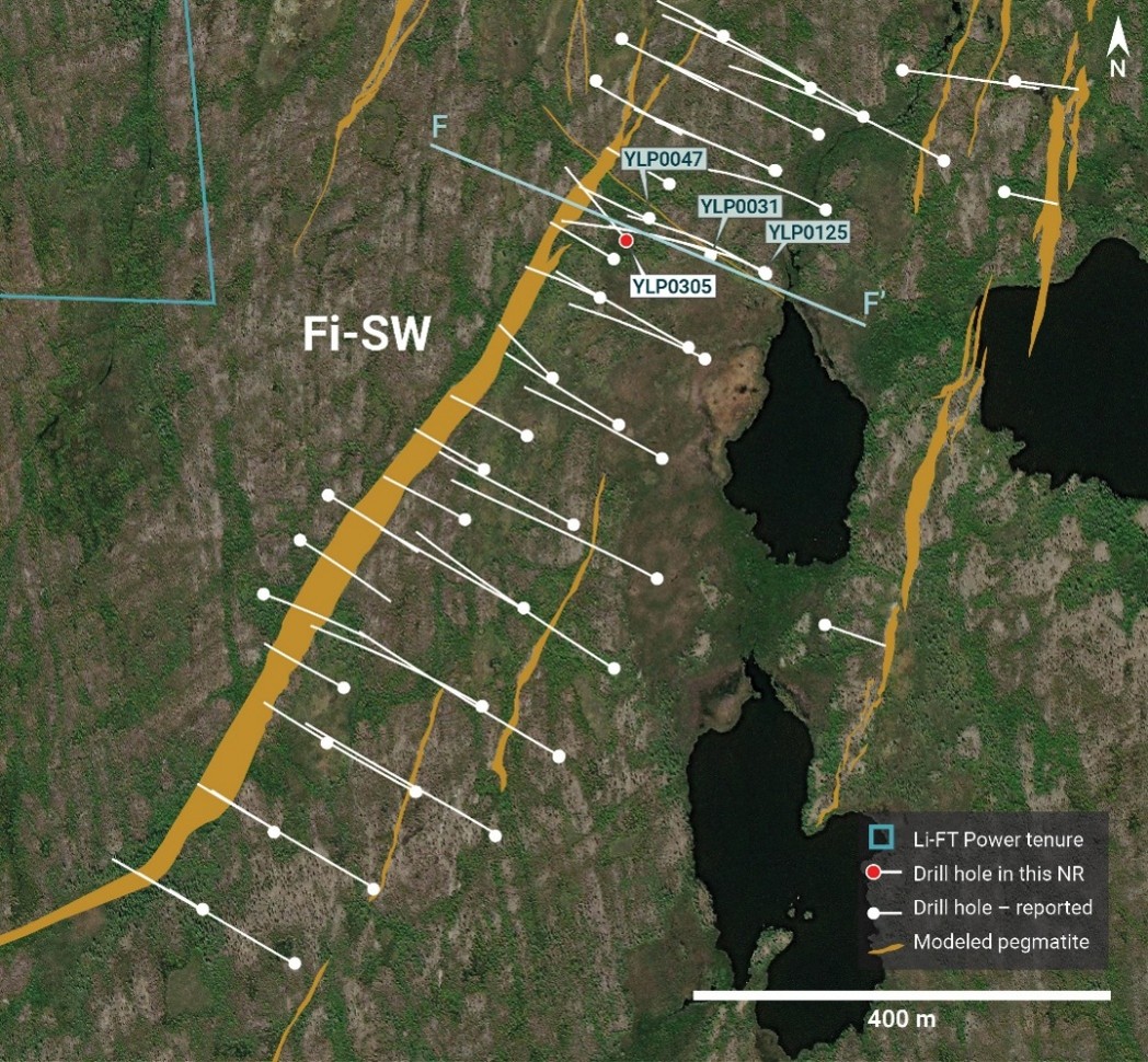
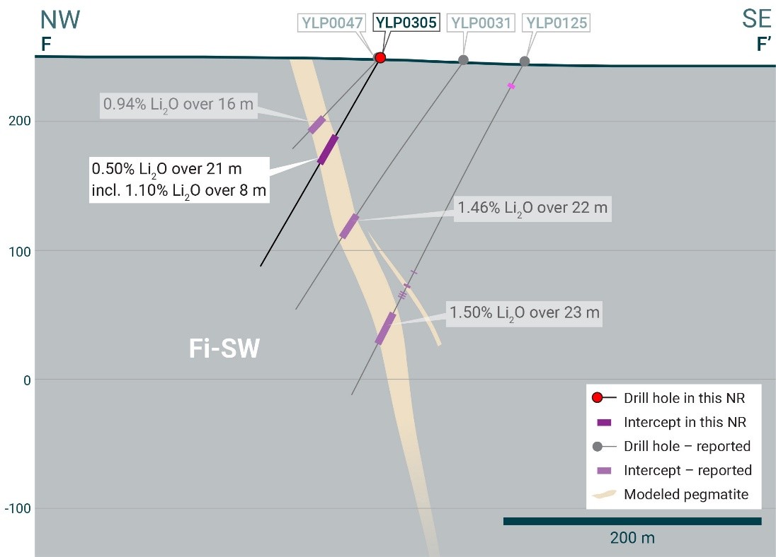
YLP-0305 was drilled near the northern end of the Fi SW pegmatite (Figure 10) to collect whole-core material for geotechnical testing. Drilling targeted the dyke 150 m below surface and offsetting 25 m down-dip from YLP-0047, which was drilled by LIFT in 2023.6 New drilling intersected a 25-m-wide pegmatite that returned a composite of 0.50% Li2O over 21 m, including 1.10% Li2O over 8 m (Appendix 1, Figure 11).
Ki Pegmatite
The Ki pegmatite complex comprises a north-northwest trending corridor of dykes that extends for at least 1.3 km on surface and dips steeply to the southwest. The southern part of the corridor consists mostly of one large dyke and several narrower flanking dykes that sum to a pegmatite width of approximately 25 m. The northern end of the complex consists of two relatively thick dykes that are located 50-150 m apart.
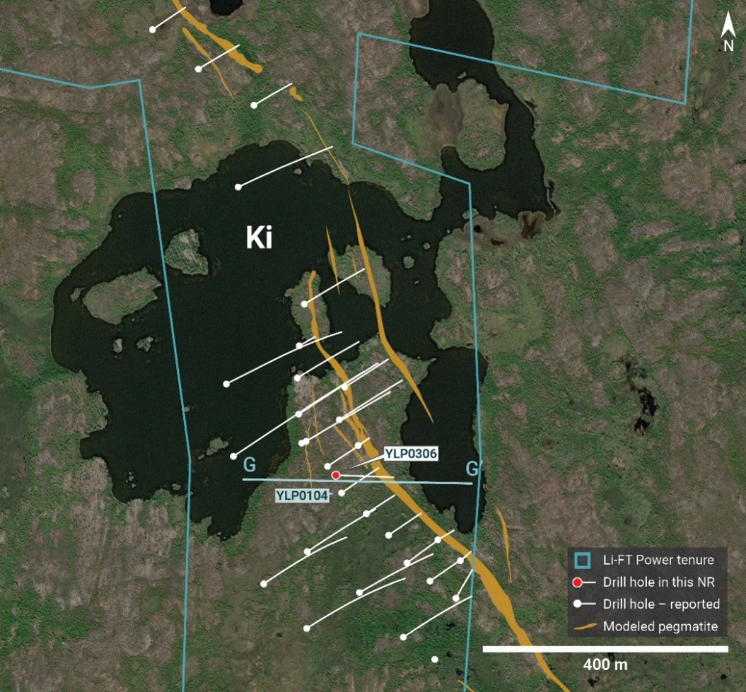
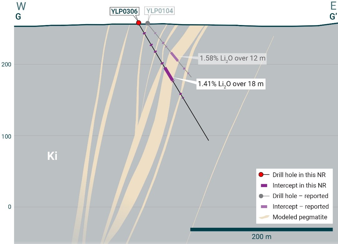
YLP-0306 was drilled in the centre of the dyke complex (Figure 12) to collect whole rock material for geotechnical testing. The hole targeted the dyke 100 m below surface, offsetting 25 m downdip from 2023 drill hole YLP-104.6 New drilling intersected a 23 m wide pegmatite dyke that returned a composite of 1.41% Li2O over 18 m (Appendix 1, Figure 13).
Figure 8 – Plan map showing Fi tenure boundary, pegmatite dykes, 2023-20247 drill holes, and the 2025 geotechnical drill hole.
Figure 9 – Section E-E’ (refer to Figure 8) looking north and showing the Fi Main pegmatite.7
Figure 10 – Plan map showing Fi tenure boundary, pegmatite dykes, 2023-2024 drill holes8, and the 2025 geotechnical drill hole.
Figure 11 – Section F-F’ (refer to Figure 10) looking northeast and showing the Fi SW pegmatite.8
Figure 12 – Plan map showing Ki tenure boundary, pegmatite dykes, 2023-2024 drill holes9, and the 2025 geotechnical drill hole.
Figure 13 – Section G-G’ (refer to Figure 12) looking north and showing the Ki pegmatite.9
General Statements
All winter 2026 holes described in this news release were drilled broadly perpendicular to the dyke orientation so that the true thickness of reported intercepts will range somewhere between 65-100% of the drilled widths.
The summer 2025 geotechnical holes were drilled slightly oblique to resource definition holes to capture more material for geotechnical testing, so that true widths are approximately 50-90% of drilled widths.
A collar header table for the drill holes in this news release is provided in Appendix 1.
Visual core logging, mineralogical studies, and metallurgical work confirm that the predominant host mineral for lithium is spodumene.
QAQC
All drill core samples were collected under the supervision of LIFT employees and contractors. Drill core was transported from the drill platform to the core processing facility where it was logged, photographed, and split by diamond saw prior to being sampled. Samples were then bagged, and blanks and certified reference materials were inserted at regular intervals. Field duplicates consisting of quarter-cut core samples were also included in the sample runs. Groups of samples were placed in large bags, sealed with numbered tags in order to maintain a chain-of-custody, and transported from LIFT’s core logging facility to ALS Labs (“ALS”) laboratory in Yellowknife, Northwest Territories.
Sample preparation and analytical work for this drill program were carried out by ALS. Samples were prepared for analysis according to ALS method CRU31: individual samples were crushed to 70% passing through 2 mm (10 mesh) screen; a 1,000-gram sub-sample was riffle split (SPL-21) and then pulverized (PUL-32) such that 85% passed through 75-micron (200 mesh) screen. A 0.2-gram sub-sample of the pulverized material was then dissolved in a sodium peroxide solution and analysed for lithium according to ALS method ME-ICP82b. Another 0.2-gram sub-sample of the pulverized material was analysed for 53 elements according to ALS method ME-MS89L. All results passed the QA/QC screening at the lab, all inserted standards and blanks returned results that were within acceptable limits.
This release is authorised by the Board of Directors of Li-FT Power Ltd.
For further information, please contact:
Francis MacDonald
Daniel Gordon
Chief Executive Officer
Investor Relations Manager
Tel: + 1.604.609.6185
Tel: +1.604.609.6185
Email: investors@li-ft.com
Email: investors@li-ft.com
Website: www.li-ft.com
About LIFT
LIFT is focused on developing a portfolio of hard rock lithium assets in Canada, with core development assets in both Quebec and the Northwest Territories. The Company owns the Yellowknife Lithium Project in the Northwest Territories and the Adina Lithium Project in the Eeyou Istchee James Bay region of Quebec. LIFT also holds early-stage exploration properties in both jurisdictions.
Qualified Person
The disclosure in this news release of scientific and technical information regarding LIFT’s mineral properties has been reviewed and approved by Ron Voordouw, Ph.D., P.Geo., Partner, Director Geoscience, Equity Exploration Consultants Ltd., and a consultant to Li-FT Power Ltd. He is a Qualified Person as defined by National Instrument 43-101 Standards of Disclosure for Mineral Projects (NI 43-101) as well as a member in good standing with the Northwest Territories and Nunavut Association of Professional Engineers and Geoscientists (NAPEG) (Geologist Registration number: L5245).
Competent Person’s Statement
Information in this announcement that relates to exploration results is based on and fairly represents information and supporting documentation obtained by LIFT and reviewed and approved by Mr. Ben Eggers, MAIG, P.Geo., Senior Geologist, SGS Canada Inc. - SGS Geological Services, a Competent Person who is a Member of the Australian Institute of Geoscientists. Mr. Eggers has sufficient experience that is relevant to the style of mineralisation and type of deposit under consideration and to the activity which he is undertaking to qualify as a ‘Competent Person’ as defined in the 2012 Edition of the ‘Australasian Code for Reporting of Exploration Results, Mineral Resources and Ore Reserves’ (“JORC Code”). Mr. Eggers is an independent consultant with SGS Canada Inc. - SGS Geological Services and Mr. Eggers consents to the inclusion in this announcement of the matters based on this information in the form and context in which it appears.
Past Exploration Results and Mineral Resource estimates referenced in this announcement were first reported by the Company in accordance with ASX Listing Rules 5.7 and 5.8 in its Prospectus lodged with ASIC on 13 April 2026 and ASX on 22 May 2026 (Prospectus). The Company confirms that it is not aware of any new information or data that materially affects the information included in the Prospectus and that in the case of the Mineral Resource estimates, that all material assumptions and technical parameters underpinning the estimates in the Prospectus continue to apply and have not materially changed. The Company confirms that the form and content in which the Competent Person's findings are presented here have not been materially modified from the Prospectus.
Cautionary Statement Regarding Forward-Looking Information
Certain statements included in this press release constitute forward-looking information or statements (collectively, “forward-looking statements”), including those identified by the expressions “anticipate”, “believe”, “plan”, “estimate”, “expect”, “intend”, “may”, “should” and similar expressions to the extent they relate to the Company or its management. The forward-looking statements are not historical facts but reflect current expectations regarding future results or events. This press release contains forward looking statements. These forward-looking statements and information reflect management's current beliefs and are based on assumptions made by and information currently available to the company with respect to the matter described in this new release.
Forward-looking statements involve risks and uncertainties, which are based on current expectations as of the date of this release and subject to known and unknown risks and uncertainties that could cause actual results to differ materially from those expressed or implied by such statements. Additional information about these assumptions and risks and uncertainties is contained under "Risk Factors" in the Company's latest annual information form filed on April 27, 2026, which is available under the Company's SEDAR+ profile at www.sedarplus.ca, and in other filings that the Company has made and may make with applicable securities authorities in the future. Forward-looking statements contained herein are made only as to the date of this press release and we undertake no obligation to update or revise any forward-looking statements whether as a result of new information, future events or otherwise, except as required by law. We caution investors not to place considerable reliance on the forward-looking statements contained in this press release.
Neither the TSX Venture Exchange nor its Regulation Services Provider (as that term is defined in the policies of the TSX Venture Exchange) accepts responsibility for the adequacy or accuracy of this news release.
Appendix1.
Diamond drilling hole details
Year
Hole number
NAD83zone
Easting
Northing
Elevation (m ASL)
Length (m)
Azimuth
Dip
Interval Type
From (m)
To (m)
Interval (m)
Li2O (%)
Dyke
2025
YLP0304
Zone 12N
371747
6941360
253.7
172
92
60
27
48
21
1.09
Fi Main
including
33
46
13
1.38
and
102
131
29
0.56
including
116
125
9
1.03
YLP0305
Zone 12N
371421.6
6940969
249.2
184
320
60
71
92
21
0.50
Fi SW
including
84
92
8
1.10
YLP0306
Zone 12N
373059.2
6942796
256.2
190
92
60
73
91
18
1.41
Ki
2026
YLP0308
Zone 12N
345908.4
6933357
197.3
383
121
50
No significant results
BIG East
YLP0309
Zone 12N
345868.1
6933259
200.5
356
118
52
282
292
10
0.66
BIG East
including
283
287
4
1.13
YLP0310
Zone 12N
346107
6933472
197.1
285
121
50
No significant results
BIG East
YLP0311
Zone 12N
346149.8
6933563
198.0
340
121
52
No significant results
BIG East
YLP0312
Zone 12N
346052.1
6933275
201.4
222
121
62
170
196
26
1.29
BIG East
including
177
194
17
1.65
YLP0313
Zone 12N
346066.6
6933380
197.0
254
121
51
198
208
10
1.12
BIG East
and
230
240
10
0.68
including
233
239
6
1.03
YLP0314
Zone 12N
346160.7
6933963
204.1
224
121
57
No significant results
BIG North
YLP0315
Zone 12N
345807.7
6933184
198.0
345
123
46
289
311
22
1.09
BIG East
YLP0316
Zone 12N
345787.9
6933080
198.0
338
120
55
No significant results
BIG East
YLP0317
Zone 12N
345699
6933016
200.7
419
120
60
No significant results
BIG East
YLP0318
Zone 12N
345693.8
6932903
196.7
387
121
56
289
292
3
0.65
BIG East
and
316
318
2
0.67
YLP0319
Zone 12N
345743.1
6932642
196.2
218
121
45
163
174
11
1.22
BIG East
YLP0320
Zone 12N
345651.5
6932696
186.8
309
121
50
226
230
4
0.53
BIG East
and
237
254
17
1.32
YLP0321
Zone 12N
345851.3
6932691
202.0
123
118
45
5
10
5
1.24
BIG East
and
48
50
2
0.79
and
61
66
5
1.08
and
80
81
1
1.04
YLP0322
Zone 12N
345815.4
6932715
197.0
159
121
53
70
80
10
0.97
BIG East
and
93
98
5
0.57
and
101
110
9
1.15
and
127
129
2
0.53
YLP0323
Zone 12N
345720.6
6932771
188.7
287
121
53
247
248
1
1.30
BIG East
and
256
262
6
0.82
YLP0324
Zone 12N
345901.2
6932781
195.0
129
121
45
54
65
11
1.04
BIG East
Appendix 2.
JORC CODE 2012 EDITION Table 1
Section 1 Sampling Techniques and Data
Criteria
JORC Code Explanation
Commentary
Sampling techniques
Nature and quality of sampling (e.g. cut channels, random chips, or specific specialised industry standard measurement tools appropriate to the minerals under investigation, such as down hole gamma sondes, or handheldXRF instruments,etc.). These examples should not be taken as limiting the broad meaning of sampling.
Include reference to measures taken to ensure sample representivity and theappropriate calibration of any measurement tools or systems used.
Aspects of the determination of mineralisation that are Materialto the Public Report
In cases where ‘industry standard’ work has been done this would be relatively simple (e.g. ‘reversecirculation drilling was used to obtain 1 m samples from which 3 kg was pulverised to produce a 30 g charge for fire assay’). In other cases, more explanation may be required, such as where there is coarse gold that has inherent sampling problems. Unusual commodities or mineralisation types (e.g. submarine nodules) may warrant disclosure of detailed information.
A total of 20 diamond drill holes are reported in this news release for 5,324 m ofcore.
The drill core is logged at one-metre intervals for lithology, mineralogy, metamorphic grade, alteration, mineralisation, and structure, priorto marking out sampleintervals.
Lithological and sample logging isdone digitally using MXDeposit software and database.
All pegmatite intervals plus 15% of the wall rock on either side are sampled on one-metre intervals regardless of lithological contacts. Quartz veins greater than 50cm, or at the discretion of the logging geologist, veins that exhibit sulphide mineralisation are alsosampled on one-metre intervals.
Cut lines are drawn on sampledintervals to ensure a consistent side of the core is sampled.
The sampler saws HQ core in half,with half being submitted for analysis andhalf remaining in the core box as arecord.
Drilling techniques
Drill type (e.g. core,reverse circulation,open-hole hammer, rotary air blast, auger, Bangka, sonic, etc.) and details (e.g. core diameter, triple or standard tube, depth of diamond tails, face-sampling bit or other type,whethercoreisorientedand if so, by what method,etc.).
A total of 20 diamond drill holes are reported in this news release for 5,324 m ofcore.
All holes were drilled from surface and ranged in dip from 44° to90°.
Drillhole collars were surveyed using differentialGPS.
Downhole surveys were conductedusing a gyroscopic downhole surveytool.
Drill sample recovery
Method of recording and assessing core and chip sample recoveries and resultsassessed.
Measures taken tomaximise sample recovery and ensure representative nature of the samples.
Whether a relationship exists between sample recovery and grade and whether samplebias may have occurred due to preferential loss/gainof fine/coarse material.
Core recovery is excellent (>99%), allowing for representative samplesto be taken and accurate analyses to be performed.
Logging
Whether core and chip samples have been geologically and geotechnically logged to a level of detail to support appropriate Mineral Resource estimation, mining studies andmetallurgical studies.
Whether logging is qualitativeor quantitative in nature. Core (or costean, channel, etc.) photography.
The total length andpercentage of the relevant intersections logged
Drill core is placed sequentially in wooden core boxes at the drill by the drillers and sealed with top covers for transport to a core logging and processing facility established at Yellowknife airport.
Core depth markers and box numbers were checked and the core wascarefully reconstructed in a secure corefacility.
The core is logged geotechnically on a3 m run by run basis including, core recovery, RQD, and fracturecount.
Magnetic susceptibility, conductivity, XRF (X-Ray Fluorescence), and LIBS (Laser Induced Breakdown Spectroscopy) measurements aretaken every metre.
The drill core is logged at one-metre intervals for lithology, mineralogy, metamorphic grade, alteration, mineralisation, and structure, priorto marking out sample intervals.
Lithological and sample logging isdone digitally using MXDeposit software and database.
The core is photographed both wet and dry after logging but prior to sampling.
Sub-sampling techniques and sample preparation
If core, whether cut or sawnand whether quarter, half or all core taken.
If non-core, whether riffled,tube sampled, rotary split, etc. and whether sampled wet ordry.
For all sample types, the nature, quality and appropriateness ofthe samplepreparation technique.
Quality control procedures adopted for all sub-sampling stages to maximiserepresentivity ofsamples.
Measures taken to ensure thatthe sampling is representative of the in situ materialcollected, including for instance results for field duplicate/second-half sampling.
Whether sample sizes are appropriate to the grain size ofthe material beingsampled.
All pegmatite intervals plus 15% of the wall rock on either side are sampled on one-metre intervals regardless of lithological contacts. Quartz veins greater than 50cm, or at the discretion of the logging geologist, veins that exhibit sulphide mineralisation are alsosampled on one-metreintervals.
Each sample represents one metre of drill core (minimum and maximum sample length of 1 m) and onesample may contain both pegmatite and wall rock.
Cut lines are drawn on sampledintervals to ensure a consistent side of the core is sampled.
The sampler saws HQ core in half, with half being submitted for analysis andhalf remaining in the core box as arecord.
Only one piece of core is removed from the core box at a time, and care istaken to replace the unsampled portion of the core in the core box in the original orientation.
The drill-hole number and sample intervals are clearly entered into a sample book to back up thedigital loggingfiles.
The geologist staples the portion of the uniquely numbered sample ticket at the beginning of the corresponding sample interval in the core box, and thesampler places one portion of the ticket in the samplebag.
The sample ticket book isarchived.
Quality of assay data and laboratorytests
The nature, quality and appropriateness of the assaying and laboratory procedures used and whether the techniqueis considered partial or total.
For geophysical tools, spectrometers, handheld XRF instruments, etc.,the parameters usedin determining the analysis include instrument make and model, reading times, calibrations factors applied and their derivation, etc.
Nature of qualitycontrol proceduresadopted (e.g. standards, blanks, duplicates, external laboratory checks) and whether acceptable levels of accuracy (i.e. lack of bias) and precision have been established.
Core samples are delivered to ALS in Yellowknife, NWT, Canada for sample preparation and sample pulps aresent for analysis to the ALS laboratory in North Vancouver, BC,Canada.
The ALS Yellowknife and North Vancouver facilities are ISO 9001and ISO/IEC 17025certified.
Samples are dried, weighed, and crushed to at least 70% passing 2 mm, and a 1000 g split is pulverised to at least 85% passing 75 µm (ALS Method CodePREP31B).
Ore grade Li analysis is completed ona 0.2 g sub-sample using a sodium peroxide fusion with an inductively coupled plasma atomic emission spectroscopy finish (ICP-AES) (ALS Method Code ME-ICP82b).
A trace level multi-elementgeochemical analysis is also completed on a 0.2 g sub-sample using a sodium peroxide fusion with an inductively coupled plasma mass spectrometry finish (ICP- MS) (ALS Method CodeME-MS89L).
ALS has its own internal QA/QC program, which is reported in theassay certificates, including the coarse reject and pulp duplicateassays.
Li-FT’s QA/QC program comprises the systematic insertion of standards or certified reference materials (CRMs), blanks, and field duplicates in additionto the establishment of documented sampling and analytical QAprotocols.
QC samples are inserted into thesample sequence at a frequency of approximately 1 CRM, blank, and field duplicate QC sample per 25 routine samples.
Approximately 10% of samplesassayed have been QC samples in the drilling programs from 2023 to2024.
Sample batches with suspected cross- sample contamination or certified reference materials returning assay values outside of the mean ± 3SD control limits are considered analytical failures by the Company and
Verification of sampling and assaying
The verification ofsignificant intersections by either independent or alternative company personnel.
The use of twinnedholes.
Documentation of primarydata, data entry procedures, data verification, data storage (physical and electronic) protocols.
Discuss any adjustment toassay data.
Data are verified and double-checkedby senior geologists on-site for data entry verification, error analysis, and adherence to strict analytical quality- controlprotocols.
All measured and observed data is collected digitally using theMXDeposit software anddatabase.
Location of data points
Accuracy and quality ofsurveys used to locate drill holes (collar and down-hole surveys), trenches, mine workings and other locations used in Mineral Resourceestimation.
Specification of the gridsystem used.
Quality and adequacyof topographiccontrol.
Drillhole collars were surveyed using differentialGPS.
Downhole surveys were conducted using a gyroscopic downholesurvey tool.
The grid system used was UTM NAD83, Zones 11 and 12North.
Dataspacing and distribution
Data spacing for reportingof ExplorationResults.
Whether the data spacing and distribution is sufficient to establish the degree of geological and gradecontinuity appropriate for the Mineral Resource and Ore Reserve estimation procedure(s) and classifications applied.
Whether sample compositinghas been applied
Drillhole spacing varies by deposit,from a maximum of 100m by 100m to a minimum of 50m by50m.
The Competent Person considers the drillhole spacing adequate and appropriate to establish geological and grade continuity for the deposits andfor the estimation and classification of an MRE.
The drillhole assays were compositedto 1.0 m.
Orientationof data in relation to geological structure
Whether the orientation of sampling achieves unbiased sampling of possiblestructures and the extent to which this is known, considering thedeposit type.
If the relationship betweenthe drilling orientation and the orientation of key mineralised structures is consideredto have introduced a sampling bias, this should be assessed and reported if material.
The orientation of the drillholes was typically perpendicular to theinterpreted strike of the pegmatite bodies and the orientation of the samples are consideredunbiased.
Sample security
The measures taken toensure samplesecurity.
At all times samples were in the custody and control of the Company’s representatives until delivery to the laboratory where samples were held ina secure enclosure pending processing.
Audits or reviews
The results of any audits or reviews of samplingtechniques and data
The Competent Person for Exploration Results reported here has reviewedthe field procedures used for sampling program at field and has compiled results from the original sampling and laboratory data.
No external audits were undertakenon thedata.
Section 2 Reporting of Exploration Results
Criteria
JORC Code Explanation
Commentary
Mineral tenement and land tenure status
Type, reference name/number, location and ownership including agreements or material issues with third parties such as joint ventures, partnerships,overriding royalties, native title interests, historical sites, wilderness or national park and environmental settings.
The security of the tenureheld at the time of reporting along with any knownimpediments to obtaining a licence to operate in the area.
The Yellowknife Lithium Project (YLP) consists of 13 mineral leases and one mineral claim totaling 1,504.7ha and located in theNorthwest Territories (NWT), Canada.
The 13 mineral leases comprise the Shorty, Ki, Hid, Bin, Bet, Mut, Nite,Big, Fi, Vo, Lens and Echo properties covering approximately 1,497.7ha.
The mineral claim namedDonovan covers 7ha.
The thirteen YLP leases and the single mineral claim are 100% owned and registered in the name of Erex International Ltd. (“Erex”), which is a wholly owned subsidiary of Li-FT.
Erex directly holds 100% of therights, title, and interest in theleases.
There is no known impediment to continuing operating in the areaand tenure is secure.
Exploration done by other parties
Acknowledgment andappraisal of exploration by otherparties.
Spodumene-bearing pegmatites were first described in the district by the Geological Survey of Canada (GSC)in 1943.
The spodumene occurrences on all or parts of what are now the Echo, Nite, Big, Ki, Fi, and Shorty leases were first staked and explored in the 1950’s.
Exploration on the various properties has occurred sporadically since 1955 and comprised mapping, trenching, drilling and metallurgical sampling.
Geology
Deposit type, geologicalsetting and style ofmineralisation.
The lithium deposits within the Project area are examples of lithium-caesium- tantalum (LCT)-type pegmatites.
All known LCT pegmatites are associated with convergent-margin or collisional orogens.
LCT pegmatites represent the most highly differentiated and last to crystallise components of certain granitic melts. Parental granites are typically peraluminous, S-type granites, although some Archean examples are metaluminous, I-type granites.
LCT pegmatites are enriched in the incompatible elements lithium, caesium, tin, rubidium, and tantalum, and are distinguished from other rare- element pegmatites by this diagnostic suite of elements
Drill hole Information
A summary of all information material to the understanding of the exploration results includinga tabulation of the following information for all Material drill holes:
easting and northing ofthe drill holecollar
elevation or RL (Reduced Level – elevation abovesea level in metres) of the drill holecollar
dip and azimuth of thehole
down hole lengthand interceptiondepth
holelength.
If the exclusion of this information is justified on the basis that the information is not Material and this exclusiondoes not detract from the understanding of the report, the Competent Person should clearly explain why this isthe case.
All drill hole summary location datais provided in Appendix 1 to this news release and is accurately represented in appropriate location maps and drill sections within the body of the news release.
Data aggregation methods
In reporting Exploration Results, weighting Averagingtechniques, maximum and/or minimum grade truncations (e.g. cutting of high grades) and cut-off grades are usually Material and should bestated.
Where aggregate intercepts incorporate short lengths of high-grade results and longer lengths of low-grade results, the procedure used for such aggregation should be statedand some typical examples of such aggregations should be shown in detail.
The assumptions used for any reporting of metal equivalent values should be clearlystated.
Sample length weighted averaging techniques have been applied tothe sample assayresults.
No grade top cuts have beenapplied.
Relationship between mineralisation widths and intercept lengths
These relationships are particularly important in the reporting of ExplorationResults.
If the geometry of the mineralisation with respect tothe drill hole angle is known, its nature should bereported.
If it is not known and only the down hole lengths arereported, there should be a clear statement to this effect (eg ‘down hole length, true width not known’).
All results are reported asdown-hole lengths.
The pierce point of any drillhole with the pegmatites varies from drillholeto drillhole, so most intercept widths are longer than truewidth.
The resource model considersthe intercepts in 3D and adjusts accordingly.
Diagrams
Appropriate maps and sections (with scales) and tabulations of intercepts should be includedfor any significant discovery being reported These should include, but not be limited to a plan view of drill hole collar locations and appropriate sectional views.
The appropriate maps, cross-sections and tables of intercepts are includedin thereport.
Balanced reporting
Where comprehensivereporting of all Exploration Results is not practicable, representative reporting of both low and high grades and/or widthsshould be practiced to avoid misleading reporting of Exploration Results.
All analytical results havebeen reported.
Other substantive exploration data
Other exploration data, if meaningful and material,should be reported including (but not limited to): geological observations; geophysical survey results; geochemical survey results; bulk samples – size and method of treatment; metallurgical test results; bulk density, groundwater, geotechnical and rock characteristics; potential deleterious orcontaminating substances.
All information that is considered meaningful and material hasbeen reported.
Further work
The nature and scale ofplanned further work (e.g. tests for lateral extensions or depth extensions or large-scale step-outdrilling).
Diagrams clearly highlightingthe areas of possible extensions, including the main geological interpretations and future drilling areas, provided thisinformation is not commercially sensitive.
The Company is engaged inongoing drilling and exploration work on the properties.
______________________________
1 Refer to Prospectus lodged with ASIC on 13 April 2026 and announced on ASX online on 22 May 2026. 2 For other drill holes refer to Prospectus lodged with ASIC on 13 April 2026 and announced on ASX online on 22 May 2026. 3 Refer to Prospectus lodged with ASIC on 13 April 2026 and announced on ASX online on 22 May 2026. 4 For other drill holes refer to Prospectus lodged with ASIC on 13 April 2026 and announced on ASX online on 22 May 2026. 5 For other drill holes refer to Prospectus lodged with ASIC on 13 April 2026 and announced on ASX online on 22 May 2026. 6 Refer to Prospectus lodged with ASIC on 13 April 2026 and announced on ASX online on 22 May 2026. 7 For other drill holes refer to Prospectus lodged with ASIC on 13 April 2026 and announced on ASX online on 22 May 2026. 8 Refer to Prospectus lodged with ASIC on 13 April 2026 and announced on ASX online on 22 May 2026. 9 Refer to Prospectus lodged with ASIC on 13 April 2026 and announced on ASX online on 22 May 2026.
Photos accompanying this announcement are available at: